
This release AVEVA E3D DESIGN 3.1.6 introduces welds and weld management to the Structures application. Welds (STWELD) can nowbe created on structural plates and joints, defining the weld path, and storing the weld detail information.
As a prerequisite, weld details are defined by a Weld Detail (WDET) element in the catalogue. Here the
properties of the weld such as type, throat thickness, bevel, etc. can be defined. The Weld Details can then
be referenced by catalogue or template joints, either explicitly or by using the Rules Engine.
When welds are created in Model the weld details are copied to the structural model. These details can then
later be used within Draw to create weld symbols.
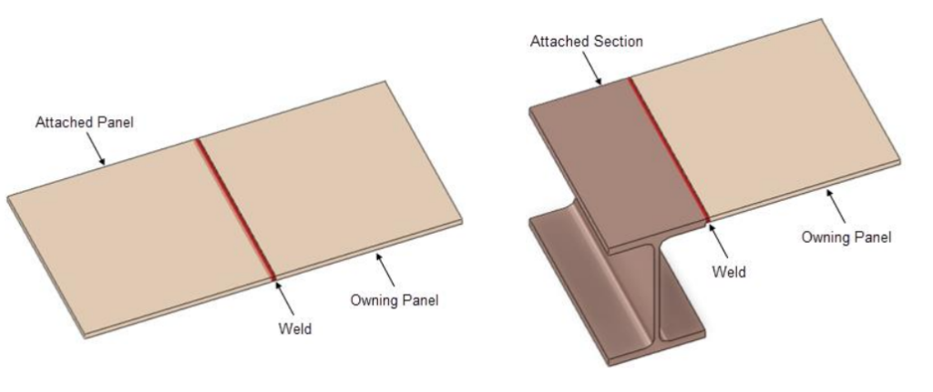
Welds can be created in Design both as part of a section joint or in relation to a Plate (Plates can be welded
together or to supporting beams). Further detail on these two workflows is explained below.
The visibility of Welds in the 3D model is an indicative representation that does not adapt to the type or size of weld, or end preparation.
If creating a template welded joint, the weld details can also be defined in the properties of the template rather than needing to refer to a WDET in the catalogue.
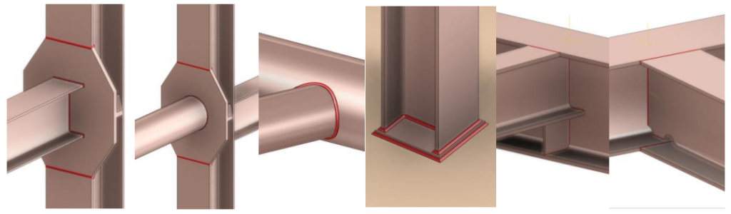
Welds in Joints
The example welded joints below have been included in the APS project. Many of these welds make use of
the Rule Engine to determine which weld detail should be selected for the given structural context.
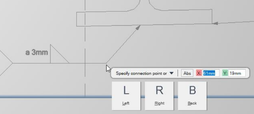
The weld position, path and detail are defined as part of the catalogue or template joint definition. Weld
path creation is aided via a tool available in the Model View form that allows the weld path to copy the profile of a defined owning section if required. Other weld paths can also be defined manually in the Model View form.
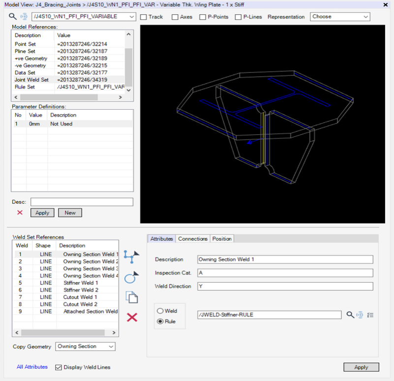
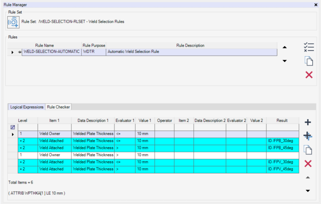
As seen in the defintion of the weld on the Model View form, the weld detail can be defined either explicitly
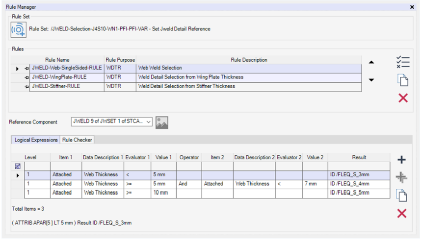
or with a rule. Creating a rule using the Rule Engine allows the weld details to vary for different attributes
of the same joint. Different rules can be written for each of the welds within the joint. Here is an example
where the weld size between the beam and wingplate changes depending on the thickness of the beam web:
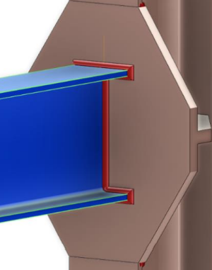
In E3D Design the welds are created when a joint specification with included welds is selected (via the Include Welds Geometry checkbox on the Create and Modify Joint forms). They are created as STWELD elements and copy the catalogue weld detail definition properties.
The connection and associated Weld can be checked and modified using the Connection Review form mentioned in the section below.
Welded joints can be used in Automatic-Joint Specifications to provide a quick and easy way of adding complete joints to the model.
Welded joints can be used in Automatic-Joint Specifications to provide a quick and easy way of adding complete joints to the model.
Welds on Plates
Welds on plates are much the same as for joints in that they are STWELD elements with similar properties.
Further, they can use the information from Structural Connection (STCONN) elements used in Bounded Plates to reference the edge that that they should be located on in response to model changes. Welds can be created between plates or between a plate and a section.
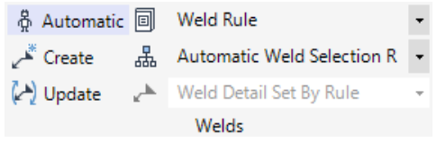
The creation of welds on Plates is controlled by a new section on the Plates ribbon. There are three primary methods of creating welds: Automatic, Create and Update. The weld details can be set either explicitly or via Rule Manger rules.
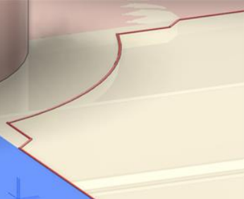
With the Automatic option, welds are automatically created when:
• Creating Bounded Plates (see right). Each weld corresponds
to a bounding or notching element.
• Splitting plates.
• Extending a plate edge.
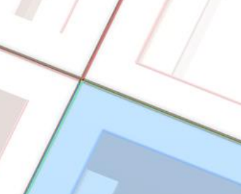
The manual Create option allows welds to be created from a selection of sections and plate:
• Plate-to-plate connections: Plates within the user selection where edges are in very close proximity to each other
(within the Maxium Tolerance value set in the Stuctural Options) have welds created in the gap between them.
• Plate-to-beam connections: Primary beams within the user selection where an edge of a plate abuts. Secondary beams within the user selection have one or two welds created between the intersecting edges depending on the
connection context.
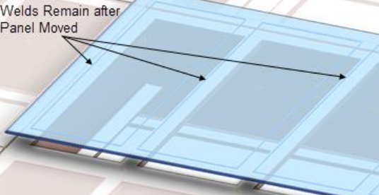
The Update function will evaluate, update, and delete welds automatically for the selected elements. These may be necessitated for scenarios such as the deletion of supporting sections, modification of section specifications, moving of panels, etc.
The weld details that are assigned to the weld can be either:
• Set explicitly using the chosen item via the Weld Detail options list.
• Set by the Rules Engine using the chosen rule selected via the options list. These rules can be defined in the catalogue and can assign different weld details depending on the logic chosen, for example, based on the thickness of the two plates being welded
Weld Symbols in Draw
In the Draw application weld symbols can be added to drawings using, and referencing, the weld details stored in the model. A weld symbol template can be associated to a Weld Detail when defined in a catalogue or template. Weld symbols for these types can then be added using the introduced Weld Label button located via the Tools group on the Auto tab. This feature utilizes the weld type and weld detail information stored in the model to automatically produce the required weld symbol and values
Example weld symbols have been included for all the example weld details included in the APS project. They are located below TT/DRA/PRJ/SYMBOLS/Structural-Weld-Symbols